Single Function Signal Generator
Emmette Cox
Product Management Coordinator
Students studying electricity will typically learn to analyze the signals in circuits by generating various waveforms in the circuits or from function generators, then viewing the graph on an oscilloscope. This activity is designed to generate a signal and graph that students can study without the need for expensive equipment.
In this activity, students use a solar-powered model, such as the dancing flowers often sold at discount variety stores. They carefully disassemble the plastic housing and attach a sensor to the capacitor, then use probeware to graph the voltage across the capacitor.
Materials
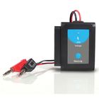
- Solar-Powered Flowers Model
- Probeware with Voltmeter
- Leads with Alligator Clips
- Magnetic Compass
- Multimeter
Safety
The capacitors in these plastic models are generally safe, but capacitors in devices that use high voltage can be dangerous. Do not access the components of any electrical device or appliance unless you are sure you can do so safely. Wear eye protection and follow all standard lab safety protocols.
Background
Many high school or first-year college physics labs investigate the RC (Resistor-Capacitor) circuit. Capacitors are circuit components that store and release charge. The lab most students perform consists of charging a capacitor and discharging the capacitor through a resistor, recording the voltage at various times and graphing the data. The graph of voltage vs. time in a discharging capacitor will be similar to figure 1. Since this activity focuses on the behavior of the capacitor, students can access their prior knowledge of RC circuits. Applying their knowledge about the behavior of capacitors to the graph generated by measuring the voltage across the capacitor in this activity helps students understand how the capacitors can be used in circuits.
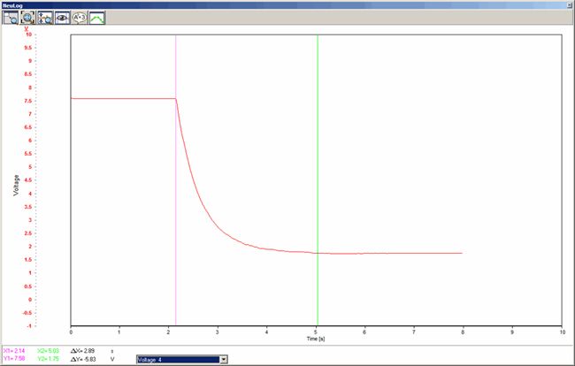
Figure 1.
Most of these solar-powered, oscillating novelties work the same way. There is a physical pendulum with a permanent magnet in the bottom of the swinging arm. Inside the plastic case, below the point where the permanent magnet hangs at rest, is a coil of wire that acts as an electromagnet. Powered by the solar cell, the electromagnet keeps the permanent magnet from coming to rest. In order to keep the pendulum swinging, the magnetic field of the coil needs to change. The circuitry inside the flower is designed to vary the current through the coil and thereby vary the magnetic field. As the capacitor charges and discharges, it varies the current. Try placing a small magnetic compass near the base of the model. When light shines on the solar cell, the model will move, and the compass needle will move back and forth as the magnetic field of the coil changes.
There are a few other components in the flower's circuit. Sometimes they are protected by a little dot of epoxy. However, this activity is only concerned with the function of the capacitor.
Procedure
- Carefully remove the plastic casing from the flower. Each model is slightly different in its construction, so it may take a minute to figure out how to disassemble the case. It's OK if the pendulum mechanism falls apart; the signal inside the circuit is unaffected by the pendulum and its permanent magnet.
- Carefully connect an alligator clip to each end of the capacitor or to the wires connected to the capacitor. The wires are delicate and there is very little space, so this may take a few tries. Do not let the 2 alligator clips touch. This will short the capacitor. It may be worth the time to solder some wires to the leads of the capacitor to make connecting with the alligator clips easier. Be careful not to melt the plastic with the soldering iron.
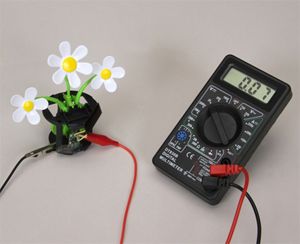
- Once the leads are attached to the capacitor, connect these to the sensor. Start with the multimeter. Set the dial to DC voltage. The display will cycle through a series of readings. Students will quickly see why the multimeter is not the best tool to analyze this circuit. The meter will cycle through a series of readings, but it will be difficult to get a full picture of what is happening using the multimeter. The meter will, however, indicate which side of the capacitor is positive. If the reading on the multimeter is negative, switch the leads.
- With the positive and negative sides of the capacitor identified, remove the multimeter and attach the probeware. Use the appropriate sensor and setting for measuring voltage. (Remember to wire the voltmeter in parallel with the capacitor; in other words, don't break the circuit, just attach a lead to each side of the capacitor.)
- Once the sensor is attached and the interface (computer, calculator, tablet, etc.) is calibrated, the display should show a graph similar to the one in figure 2.

Figure 2.
In this circuit, the capacitor will charge and discharge repeatedly. The graph shows that the time for the growth and decay of the voltage measured across the capacitor is consistent. Since the strength of the magnetic field in an electromagnet is dependent on current, the magnetic field of the coil changes. Therefore, the pendulum never comes to rest, and the solar-powered flower keeps dancing (as long as there is enough light).
From the graph, students can read the voltage across the capacitor and see how long it takes the capacitor to charge and discharge. What information can be found in the graph? What would changing the value of the capcitor do to the graph? Try shining a brighter light on the solar cell. How does this affect the graph?
The figures in this article were captured using the NeuLog™ USB Bridge Module and the NeuLog™ Voltage Sensor.