My Cart
Your Shopping Cart is currently empty. Use Quick Order or Search to quickly add items to your order!
 Emmette Cox
Product Management Coordinator for Physical Science
Carolina Biological Supply Company
Whether functioning as a single fixed pulley, part of a system of pulleys, or part of a more complex machine, a pulley multiplies the force applied by the user to move the load. Because they multiply force, pulleys provide a mechanical advantage, allowing people to lift masses much greater than they could lift on their own.
Problems with pulleys appear in physics books and physics tests quite often. In order to be successful in physics, or to continue studying physics or engineering, your students should have at least a basic understanding of what pulleys are and how they function.
In this article, you will find activities that involve taking measurements using pulley systems. All activities build on students’ prior knowledge and are based on the pulley system problems that students would typically encounter in textbooks or on tests.
Problems involving pulleys, where certain assumptions keep the problems simple, provide a great opportunity for students to apply their knowledge of mathematics, mechanics, and the laws of motion. For the purposes of this article, the following assumptions are made:
In order to stay safe while performing these activities, follow all standard laboratory safety practices and wear appropriate PPE. Support structures and rope or string should be sturdy and strong enough to support the masses used in these activities. Keep in mind that some activities involve moving parts and objects accelerating and falling under the force of gravity, which you should keep clear of.
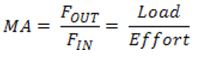
A machine is a device that makes work easier by multiplying the force applied to it. Machines do this by changing the direction or magnitude—or both— of the applied force. A force is a push or a pull applied to an object, and it is measured in pounds or newtons. The force applied to the machine may be called the effort force, the input force, or FIN. The force delivered by the machine may be called the resistance force, the output force, or FOUT. Machines provide a mechanical advantage, or MA. The mechanical advantage tells how much easier the machine is making the work for the user.
You can calculate the mechanical advantage of a machine by dividing the force the machine delivers, FOUT, by the force applied or input force, FIN.
If a machine has a mechanical advantage of 2, and the user applies a force of 10 newtons to the machine, the machine will deliver a force of 20 newtons. If you know the mechanical advantage of a machine, you can calculate the effort force you need to apply to the machine to lift or move a load. The mechanical advantage has no units, as it is a ratio of two forces.
Machines multiply force, but not work or energy. In fact, the work done by the user, the input work, is always greater than the work done by the machine, the output work.
WIN > WOUT
Work is calculated by multiplying the force by the distance the force is applied. The efficiency of the system is calculated by dividing the work done by the machine, work out (WOUT), by the work done by the operator, work in (WIN).
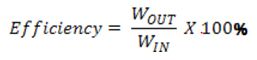
The efficiency of any machine must be less than 100%. This means the work out is always less than the work in. A machine with 100% efficiency (where WOUT = WIN) is called an ideal machine. The conditions of an ideal machine might be used in planning or designing a machine, but no ideal machine actually exists.
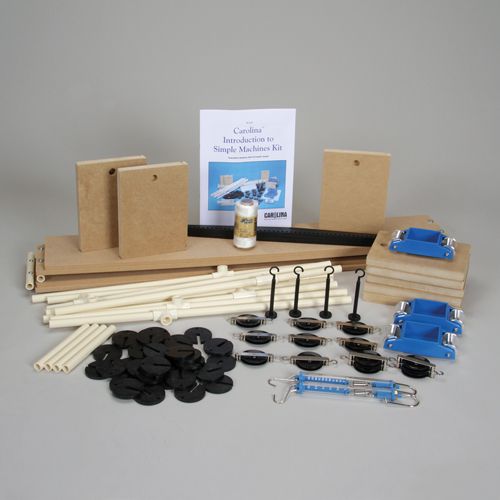
Students could frequently encounter problems asking them to use a diagram or picture to determine the mechanical advantage of a pulley system. With some basic equipment, students can build these basic systems and measure the mechanical advantage. Students can then compare their calculations with the results.
One of the six simple machines, a pulley has a unique structure consisting of a disk and an axle. The disk rotates around the axle, which runs through the disk’s center. Pulleys work by applying force to a string or a rope that passes over the disk. There is usually a groove in the disk edge to provide a track for the rope. The pulley turns as force is applied to one end of the rope, changing the direction of the force. The opposite end of the rope is attached to the object that needs to be moved, the load. The pulley multiplies the applied force by the mechanical advantage of the pulley.
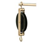
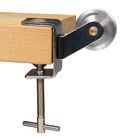
A single fixed pulley has a mechanical advantage of one. The pulley allows a person to change the direction of the force, but the force delivered by the pulley, the output force, is the same as the applied force or input force. Consider the pulley in figure 1.
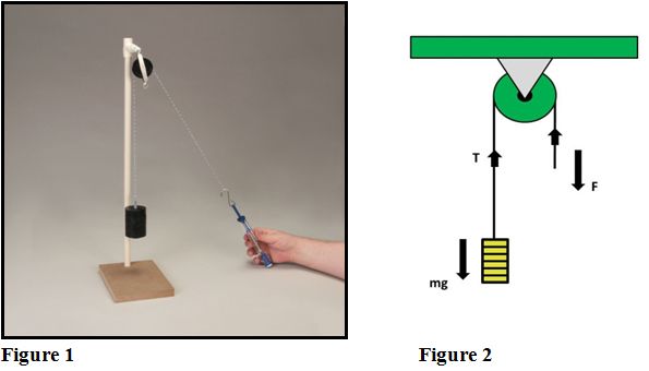
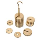
Using a spring scale makes it easy to measure the applied force in newtons (N). Materials needed to construct a similar set up to figure 1 include:
The load on the pulley is equal to the weight of the mass. To calculate the force of gravity (weight) of the mass, multiply the mass (m) in kilograms by acceleration due to gravity (g) where g = 9.8 m/s2. F represents the applied force. T is the force of tension in the rope.
F = ma = mg
Some small error from the spring scale is to be expected.
Consider figure 2. At equilibrium, the effort force, F, must equal the tension, T. Also, at equilibrium, the weight of the load must equal the tension in the lines supporting the mass. Therefore mg = T. This means F = mg. The mechanical advantage is 1.
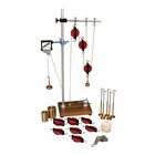
Assemble a pulley system as shown in figure 3. Parts include:
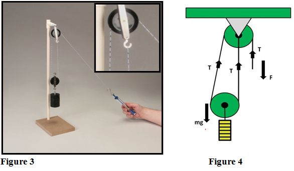
This system is designed so that two sections of the rope are supporting the load. The mechanical advantage of the system is 2. The mechanical advantage can again be calculated by examining the diagram. There are two lines supporting the load. Notice that the direction of the tension in every line is up. The effort force equals the tension in the rope where the force is applied. The tension must be the same everywhere in the rope.
For Figure 4
F = T
mg = 2T
T = ½mg
Therefore: F = ½mg
For the system in figure 4, only half the force has to be applied to the machine to move the load, but the rope that the force is applied to must move twice as far as the rope moving the load. The string has been marked in 1 cm increments to better illustrate the difference in the distance each rope moves.
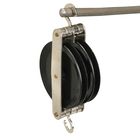
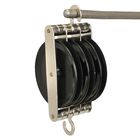
The system in figure 5 has a mechanical advantage of 3 and requires a double pulley at the top position. The system in figure 6 has a mechanical advantage of 4 and requires two double pulleys.
Try assembling these systems and calculating the mechanical advantage. Parts for the systems in figures 5 and 6 include:
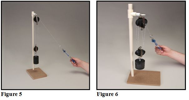
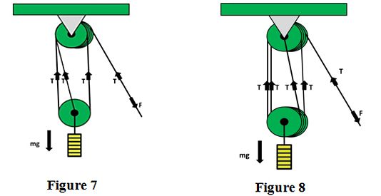
For Figure 7 For Figure 8
F = T F = T
mg = 3T mg = 4T
T = ⅓mg T = ¼mg
Therefore: F = 1/3 mg Therefore: F = 1/4 mg
MA = 3 MA = 4
Pulleys have many applications, one of which is construction. Cranes use pulleys to lift building materials into place to build all manner of structures. Automobiles rely on pulleys as well. Inside some engines, you can find systems of pulleys and belts to transfer energy from the motor to the fan or the alternator. With the help of a pulley system, it’s also possible to lift the weight of a car’s engine.
Now that you have a basic understanding of pulley structure and function, can you assemble a system with a greater mechanical advantage than the examples shown here? What other applications of pulleys can you find? How can the calculations for mechanical advantage or efficiency be used to design a pulley system or other machine?
Here are some resources you can use in your investigation of pulleys: